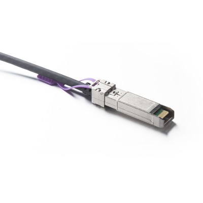
What's DSFP?
DSFP host application reference circuit where a DSFP module is plugged into the host shown inFigure 14. The logical host controls signals2 are designated as H_RSTn, H_INT, H_LPWn, andH_PRSn and the logical module control signal are designated as M_RSTn, M_INT, M LPWn.Figure 14 also provide suggested host board power supply filters for a 3.3V supply. lf an alternatecircuit is used for power supply filtering, then the same filter characteristics as DSFp Host filter isrequired. The 2-wire SCL/SDA pull resistors of 3.3 kΩ shown on the reference diagram is de-signed to support 400 kHz bus speed with 100 pf load capacitance.
DSFP host application reference circuit where an SFP+ module is plugged into thehost shown in Figure 15. The DSFP host must provide appropriate protection to prevent damageto the transmitter outputs TD2+/- connected respectively to the module TX Fault and Gnd. it isrecommended that DSFP host only turns on the TD2+/TD2- after the module has been identifiedas a DSFP. SFP+ module RX LOS and RS1 contacts respectively are connected to the DSF Phost RD2+/RD2- inputs. AC coupling RD2+/RD2- inputs are required to prevent damage to thehigh speed SerDes inputs from LVTTL levels of RX LOS and RS1. The value of AC coupling ca-pacitor depends on the application with capacitor size large enough to limit the impact of the base.line wander. The location of AC coupling capacitors on TD2+/- and RD2+/- signal lines could be atany of the following locations; mounted on the host PCB, integrated into the host ASlC package, orintegrated into the host ASlC die.

More Information
| CPN | CAB-D56/D56-P | Model | CAB-D56/D56-P |
|---|---|---|---|
| Spec. AWG | 30 | Rate | 100G |
| Multi Rate | multi-rate | Spec. P/A | Passive |
| Brand | 10Gtek |
warranty & Service
questions
Reviews
Write Your Own Review


